Product: Instant Digital Download (PDF)
Diagnose left-front, right-front, left-rear, and right-rear ABS wheel-speed sensor circuit and signal faults—including open circuits, supply voltage, short-to-ground/power checks, installation direction, air-gap/knuckle deformation, contamination, and drive-shaft/wheel-bearing tone-ring faults—using the OEM guided diagnostic procedure and connector pinout diagrams.
Years Covered:
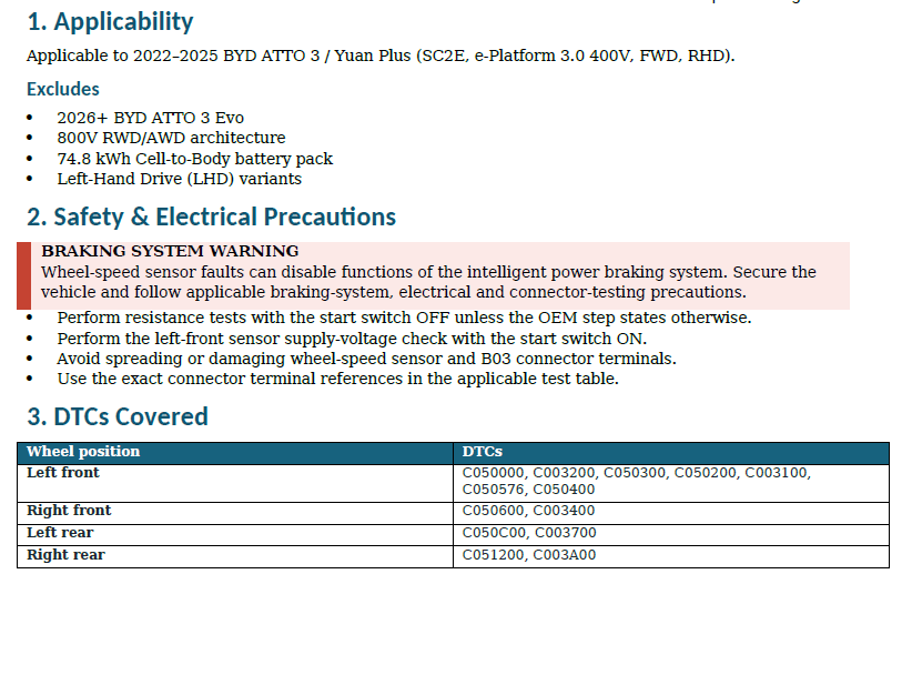
2022, 2023, 2024, 2025
Vehicle Specification:
SC2E, e-Platform 3.0 400V, FWD, RHD — ABS / Intelligent Power Braking System
Excludes:
2026+ BYD ATTO 3 Evo, 800V RWD/AWD architecture, 74.8 kWh Cell-to-Body battery pack, and Left-Hand Drive (LHD) variants.
DTCs Covered
- Left Front: C050000 (Open Circuit), C003200 (Low Supply Voltage), C050300 (Signal-to-Power Short), C050200 (Signal-to-Ground Short), C003100 (Signal Fault), C050576 (Incorrect Installation Direction), C050400 (Abnormal Air Gap)
- Right Front: C050600 (Open Circuit), C003400 (Signal Fault)
- Left Rear: C050C00 (Open Circuit), C003700 (Signal Fault)
- Right Rear: C051200 (Open Circuit), C003A00 (Signal Fault)
Diagnostic Coverage
- OEM intelligent power braking safety and electrical testing precautions
- Electro-hydraulic braking DTC confirmation and intermittent-fault evaluation
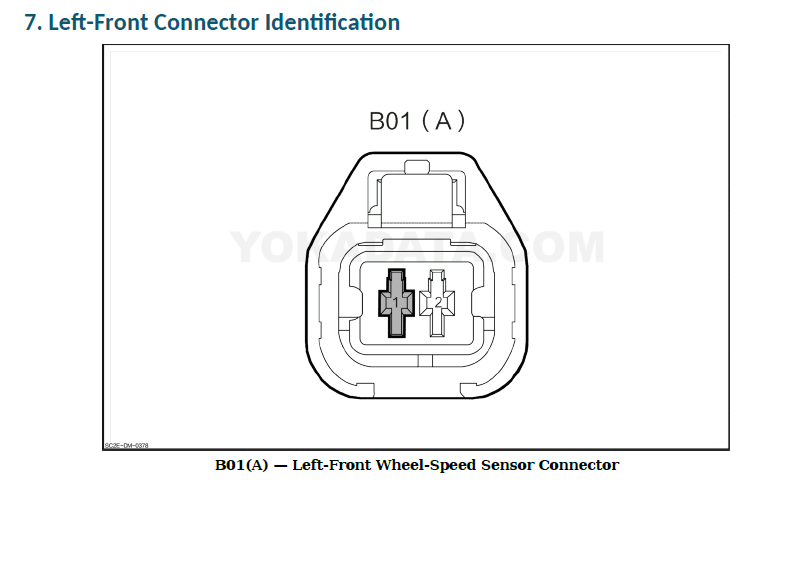
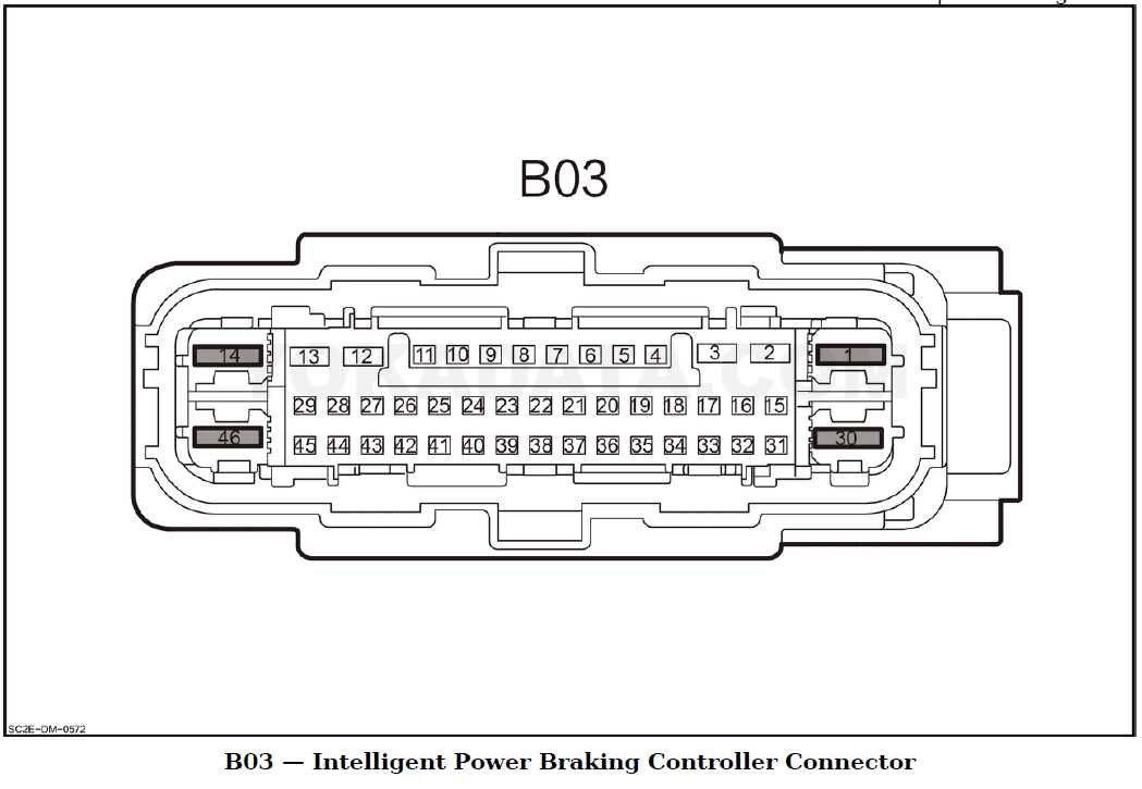
- Left-front (B01(A)), right-front (B01(B)), left-rear (K08(A)), and right-rear (K08(B)) pin-to-pin continuity checks to Intelligent Power Braking Controller connector B03 (< 1 Ω)
- Left-front sensor supply voltage (11–14 V) and short-circuit isolation testing (> 10 kΩ)
- Sensor installation orientation, steering-knuckle deformation, drive-motor shaft gear-ring, and rear wheel-bearing tone-ring inspection branches
- OEM Connector Identification Diagrams: Highlighted terminal pinouts for Left-Front Wheel-Speed Sensor B01(A) and Intelligent Power Braking Controller B03
- Consolidated Circuit Specification Summary table and OEM-directed replacement branches
Included Links to OEM Source Material
The guide includes reference links to:
- Complete OEM Diagnostic Manual
- Electronic Wiring Diagram
- Repair Manual
These are reference links to related OEM source material and are not bundled documents included with this Diagnostic Guide.