Product: Instant Digital Download (PDF)
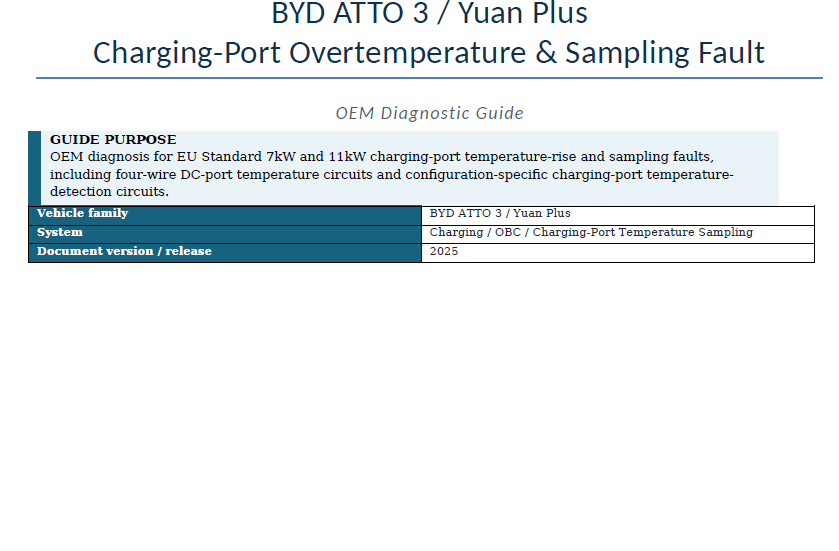
Diagnose charging-port overtemperature and temperature-sampling faults using the OEM diagnostic procedures for EU Standard 7kW and 11kW charging configurations, including charging-port temperature circuits, wiring and connector checks, resistance testing, controller-to-port continuity checks, charging-port inspection and controller software diagnosis.
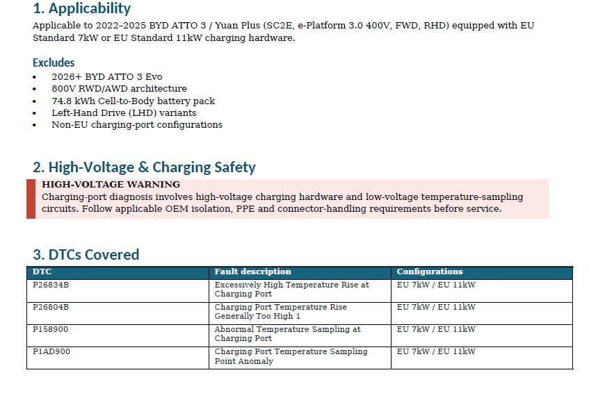
Years Covered:
2022, 2023, 2024, 2025
Vehicle Specification:
SC2E, e-Platform 3.0 400V, FWD, RHD, EU Standard 7kW or EU Standard 11kW charging configuration
Excludes:
2026+ BYD ATTO 3 Evo, 800V RWD/AWD architecture, 74.8 kWh Cell-to-Body battery pack, Left-Hand Drive (LHD) variants, and non-EU charging-port configurations.
DTCs Covered
- P26834B — Excessively High Temperature Rise at Charging Port
- P26804B — Charging Port Temperature Rise Generally Too High 1
- P158900 — Abnormal Temperature Sampling at Charging Port
- P1AD900 — Charging Port Temperature Sampling Point Anomaly
Diagnostic Coverage
- OEM high-voltage and charging-system safety precautions
- EU Standard 7kW and 11kW configuration-specific diagnosis
- VDS DTC confirmation, clearing and fault-code recheck
- Intermittent/sporadic fault diagnosis
- P26834B charging-port excessive-temperature-rise diagnosis
- P26804B charging-port temperature-rise diagnosis
- P158900 charging-port temperature-sampling diagnosis
- P1AD900 charging-port temperature-sampling-point diagnosis
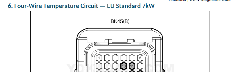
- EU Standard 7kW four-wire temperature circuit:
- B53-7 / B53-8 / B53-9 / B53-10
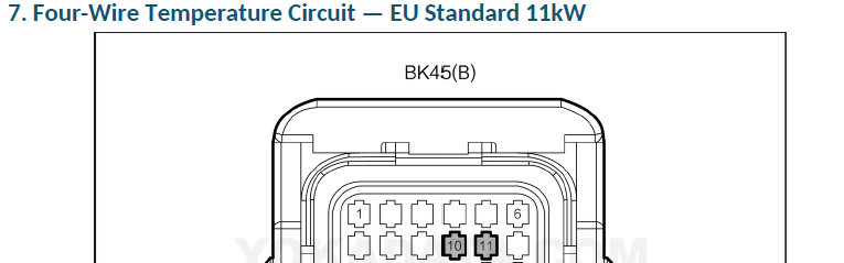
- BK45(B)-18 / BK45(B)-17 / BK45(B)-11 / BK45(B)-10
- EU Standard 11kW four-wire temperature circuit:
- B53_3-1 / B53_3-2 / B53_3-3 / B53_3-4
- BK45(B)-18 / BK45(B)-17 / BK45(B)-11 / BK45(B)-10
- P158900 EU Standard 7kW temperature-detection circuit:
- P158900 EU Standard 11kW temperature-sampling circuits:
- B53_3-6 → BK45(A)-9
- B53_3-8 → BK45(A)-23
- B53_3-18 → BK45(A)-7
-
Temperature-sampling circuit short-to-ground testing: > 10 kΩ
-
Temperature-sampling circuit short-to-power testing: > 10 kΩ
-
Charging-port-to-controller continuity testing: < 1 Ω
-
Configuration-specific OEM charging-port and controller connector identification
-
AC/DC charging-port inspection for dirt, burn marks and other faults
-
Wiring-harness inspection and repair/replacement decision paths
-
Charging-port repair/replacement paths where applicable
Included Links to OEM Source Material
Reference links are provided within the guide for:
- Complete OEM Diagnostic Manual
- Electronic Wiring Diagram
- Repair Manual
The linked OEM source documents are separate reference resources and are not included with this Diagnostic Guide.